Ring Mod
- May 21, 2021
- 3 min read
Updated: Jul 2, 2021
Stereo effect using the waveform object to create a selection of waveforms to ring modulate with the guitar input signal. Ring modulating is done with the multiply object. There's a variable low pass filter at the output and a bit of make-up gain after it.
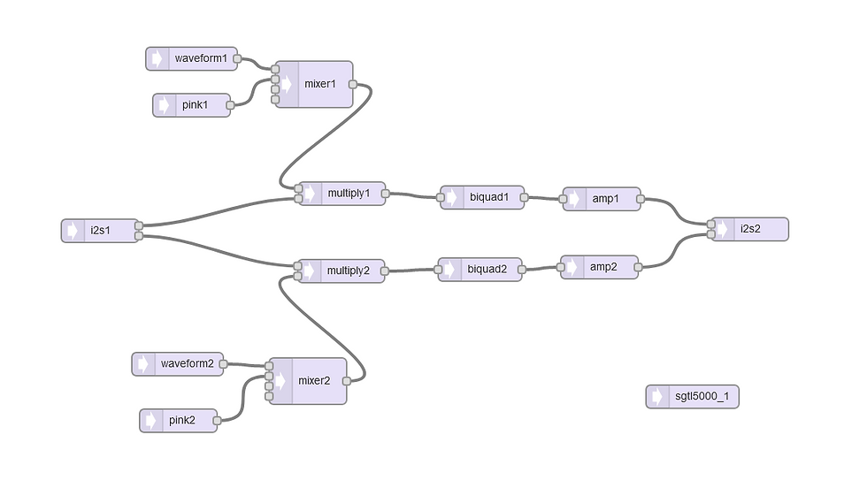
I didn't include the variable triangle waveform or the arbitrary waveform, opting instead to ring modulate the guitar signal with pink noise, which sounds errr.... These are the waveforms available, from counter-clockwise to clockwise on pot A0:
WAVEFORM_SINE
WAVEFORM_SAWTOOTH
WAVEFORM_SAWTOOTH_REVERSE
WAVEFORM_SQUARE
WAVEFORM_TRIANGLE
WAVEFORM_PULSE
WAVEFORM_SAMPLE_HOLD
PINK NOISE
A0 = waveform select, A1 = waveform frequency, A2 = low pass filter.
I haven't used pot A3, the toggle or the footswitch.
#define LED 3
#include <Bounce.h>

#include <Audio.h>
#include <Wire.h>
#include <SPI.h>
#include <SD.h>
#include <SerialFlash.h>

// GUItool: begin automatically generated code
AudioInputI2S            i2s1;           //xy=328,397
AudioSynthWaveform       waveform2;      //xy=428,569
AudioSynthNoisePink      pink2; //xy=429,642
AudioSynthWaveform       waveform1;      //xy=446,175
AudioSynthNoisePink      pink1;          //xy=446,235
AudioMixer4              mixer2; //xy=596,591
AudioMixer4              mixer1;         //xy=604,208
AudioEffectMultiply      multiply2; //xy=639,449
AudioEffectMultiply      multiply1;      //xy=640,349
AudioFilterBiquad        biquad2; //xy=818,447
AudioFilterBiquad        biquad1;        //xy=821,354
AudioAmplifier           amp2; //xy=972,444
AudioAmplifier           amp1;           //xy=975,356
AudioOutputI2S           i2s2;           //xy=1166,395
AudioConnection          patchCord1(i2s1, 0, multiply1, 1);
AudioConnection          patchCord2(i2s1, 1, multiply2, 0);
AudioConnection          patchCord3(waveform2, 0, mixer2, 0);
AudioConnection          patchCord4(pink2, 0, mixer2, 1);
AudioConnection          patchCord5(waveform1, 0, mixer1, 0);
AudioConnection          patchCord6(pink1, 0, mixer1, 1);
AudioConnection          patchCord7(mixer2, 0, multiply2, 1);
AudioConnection          patchCord8(mixer1, 0, multiply1, 0);
AudioConnection          patchCord9(multiply2, biquad2);
AudioConnection          patchCord10(multiply1, biquad1);
AudioConnection          patchCord11(biquad2, amp2);
AudioConnection          patchCord12(biquad1, amp1);
AudioConnection          patchCord13(amp2, 0, i2s2, 1);
AudioConnection          patchCord14(amp1, 0, i2s2, 0);
AudioControlSGTL5000     sgtl5000_1;     //xy=1092,611
// GUItool: end automatically generated code


Bounce footswitch = Bounce(0, 50);  // debounce the footswitch
Bounce D1 = Bounce(1, 50);          // debounce the toggle switch
Bounce D2 = Bounce(2, 50);          // "  "  "  "  "  "  "  "  "

// check the toggle position
bool right;
bool middle;
bool left;
void checkToggle () {               // our function to check toggle position
D1.update();  D2.update();          // check digital inputs connected to toggle
if(digitalRead(1) && !digitalRead(2))   {right = 1; middle = 0; left = 0;}  // toggle is right
if(digitalRead(1) && digitalRead(2))  {right = 0; middle = 1; left = 0;}  // toggle is in the middle
if(!digitalRead(1) && digitalRead(2))   {right = 0; middle = 0; left = 1;}  // toggle is left
}

byte wavepot;
byte waveform;
int pitch;
int lpf;

void setup() {

  AudioMemory(40); // the "40" will vary depending on your effect, eg. a delay effect will require more memory .... (HOW MUCH?)
  sgtl5000_1.enable(); // this turns on the SGTL5000, which is the audio codec on the audio board
  sgtl5000_1.volume(1);  // this sets the output volume (it can be between 0 and 1)
  sgtl5000_1.inputSelect(AUDIO_INPUT_LINEIN); // selects the audio input, we always use Line In
  analogReadResolution(12); // configure the pots to give 12 bit readings
  pinMode(0, INPUT_PULLUP); // internal pull-up resistor for footswitch
  pinMode(1, INPUT_PULLUP); // internal pull-up resistor for toggle
  pinMode(2, INPUT_PULLUP); // internal pull-up resistor for toggle
  pinMode(3, OUTPUT);       // pin 3 (the LED) is an output;
  Serial.begin(9600);       // initiate the serial monitor. USB is always 12 Mbit/sec

  // waveform set up
  waveform1.offset(0);
  waveform2.offset(0);
  pink1.amplitude(1);
  pink2.amplitude(1);

  // make up gain
  amp1.gain(2);
  amp2.gain(2);
}

void loop() {

  // A0 = waveform
  wavepot = analogRead(A0) >> 9;
  if(wavepot == 0) waveform = WAVEFORM_SINE;
  if(wavepot == 1) waveform = WAVEFORM_SAWTOOTH;
  if(wavepot == 2) waveform = WAVEFORM_SAWTOOTH_REVERSE;
  if(wavepot == 3) waveform = WAVEFORM_SQUARE;
  if(wavepot == 4) waveform = WAVEFORM_TRIANGLE;
  if(wavepot == 5) waveform = WAVEFORM_PULSE;
  if(wavepot == 6) waveform = WAVEFORM_SAMPLE_HOLD;
  if(wavepot == 7) {       // pink noise
     mixer1.gain(0, 0);
     mixer1.gain(1, 1);
     mixer2.gain(0, 0);
     mixer2.gain(1, 1);
  }
  else {
    mixer1.gain(0, 1);
    mixer1.gain(1, 0);
    mixer2.gain(0, 1);
    mixer2.gain(1, 0);
  }

  // A1 = frequency
  pitch = (analogRead(A1) << 1) + 1; // frequency is 1 to 8189

  // set waveform
  waveform1.begin(1, pitch, waveform);
  waveform2.begin(1, pitch, waveform);


  // A2 = low pass filter
  lpf = analogRead(A2) + 1000;
  biquad1.setLowpass(0, lpf, 0.8);
  biquad2.setLowpass(0, lpf, 0.8);


}


Comments