Intro to STM32 Blackpill for Audio FX
- Jan 13, 2023
- 3 min read
Updated: Jan 15, 2024
You can program the Blackpill board with the Arduino IDE, but it generates very inefficient code that will slow your program right down. Instead I use STMicrocontrollers' Cube IDE . It provides a library of functions for easily reading / writing pins etc called HAL, more than fast enough for music stuff.
Cube IDE also provides a graphical interface (called IOC) for setting up which pins you want to use etc, it then generates this as code into your main.c file. Only edit the main.c file within the 'USER CODE BEGIN...' sections, further edits to the IOC will then update your main file without affecting the code you've written.
The following is a bunch of extra bits for reading / writing samples and pots etc...
Setting up multiple ADCs with DMA
DMA is a background process of moving data around. It will continuously read multiple ADCs and store the readings in an array. I use ADCs for the audio input and pots.
This code comes from Random Rick on Youtube, like subscribe and so on! This is the process for setting up DMA as shown in Rick's vid:
In the IOC tab:
Categories (on left) > Analog > ADC
Select your multiple ADC channels under Mode (or on image of chip)
Under Parameter Settings, set Scan Conversion Mode to Enabled
Scroll down, set Number of Conversions to how many ADC channels you have
Check each ADC Channel has an assigned Rank, and Sampling Time is more cycles than number of 'ADC clock cycles' (shown next to 'resolution')
Under DMA settings, add your ADC (the only option there) - you can change data size here if needs be, I'm using 'bytes' as my samples / ADC readings are 8bit
Check there are no errors (coloured) in Clock Configuration and set to max speeds possible (scroll down for clock config info)
Save IOC (device configuration) and generate code
In the code (main.c) view:
Declare these DMA Variables and Function above main():
 // DMA
volatile unsigned char adcResultsDMA [4];
const int adcChannelCount = sizeof (adcResultsDMA) / sizeof (adcResultsDMA[0]);
volatile int adcConversionComplete = 0;
void HAL_ADC_ConvCpltCallback(ADC_HandleTypeDef *hadc)
{
	adcConversionComplete = 1;
}
"unsigned char" for 8bit stuff ... "[4]" is number of ADCs you're using
In your main while(1) loop, continuously start conversions with:
HAL_ADC_Start_DMA(&hadc1, (byte*) adcResultsDMA, adcChannelCount);
while(adcConversionComplete == 0)
{}
adcConversionComplete = 0;
and get results from the array like:
sample = adcResultsDMA[0];PWM set-up
I use PWM to write the audio output. It needs a basic analog filter after it, you'll find a >basic one on my Blackpill template schematic. Set up the PWM like so:
In IOC:
Select 'Timers' (on left) and pick a timer for the PWM (I use Timer 2)
Set Clock Source to Internal Clock
Scroll down, 'Counter Period' sets bit depth, type '255' for 8 it stuff
Enable 'auto reload- preload'
In the top box, set 'Channel 1' to 'PWM Generation CH1'
In main.c:
Start the PWM by including this under "USER CODE BEGIN 2":
HAL_TIM_PWM_Start(&htim2, TIM_CHANNEL_1);Set PWM duty cycle (write output samples) with:
TIM2->CCR1 = output; // "output" is your audio sample PWM will be output on pin A0.
us Delay set-up
A microsecond delay is handy for a master clock speed (think sample rate control) among other things. The following code comes from here.
In IOC:
Select new timer, change Clock Source to Internal Clock
Set Prescaler value to 99 (since clock config set to 100mhz)
In main.c:
Delay function (check "&htim1" matches your selected timer):
void delay_us (uint16_t us){__HAL_TIM_SET_COUNTER(&htim1,0);  // set the counter value a 0while
(__HAL_TIM_GET_COUNTER(&htim1) < us);  // wait for the counter to reach the us input in the parameter}
Start the timer in main (but not in the continuous while loop) like so:
HAL_TIM_Base_Start(&htim1);For a 10 millisecond delay, write:
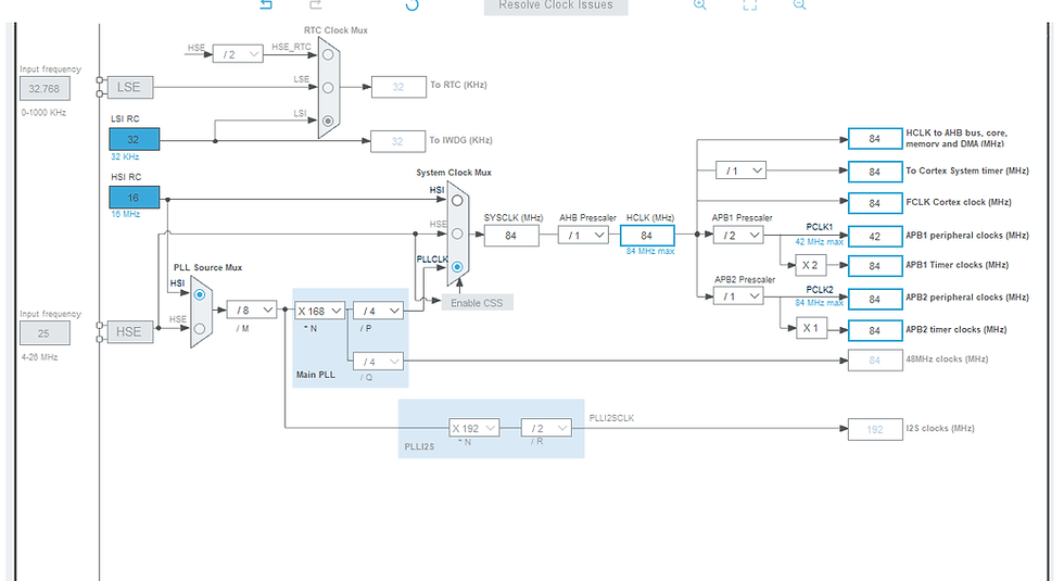
delay_us(10);Clock config
This is how I set up the internal clock to max speeds possible:
HAL
Here's a few common HAL commands I'm often using. You have to turn each pin on in the IOC first for these to work.
Read a digital pin:
if((HAL_GPIO_ReadPin(GPIOB, GPIO_PIN_6) == GPIO_PIN_SET) {...}check if pin B6 is HIGH
if((HAL_GPIO_ReadPin(GPIOB, GPIO_PIN_6) == GPIO_PIN_RESET) {...}check if pin B6 is LOW
Write a digital pin:
HAL_GPIO_WritePin(GPIOA, GPIO_PIN_12, SET);set pin A12 as HIGH
HAL_GPIO_WritePin(GPIOA, GPIO_PIN_12, RESET);set pin A12 as LOW
System timer:
uint32_t currentMillis = 0;
uint32_t previousMillis = 0;
uint16_t time = 20;

currentMillis = HAL_GetTick();                // get system tick
if(currentMillis - previousMillis >= time)    // if enough time passed
{
    // do something...
    previousMillis = currentMillis;           // reset timer
}
HAL_GetTick() returns the number of system ticks, which is dependent on your IOC clock settings. You can set them to be one millisecond if you desire. I use this code as a debounce timer, only checking footswitches/toggles every 20ms or so.


Comments